Check Terminal Box Markings
It is marked on the terminal box as U1, V1, W1 and U2, V2, W2. The markings according to IEC, define the starting and ending points of the windings and therefore make the job of installers easier, taking a few hours or even minutes to complete. For instance, in industrial motors—in manufacturing, power and energy, mining and oil extraction, the chemical industry, food processing—the markings are usually located on the terminal box or near the terminal connections, about 5 cm apart.
Especially for equipment running for over 15 years, the following methods can be used:
-
Multimeter Testing: Perform resistance testing between the windings, typically ranging from 5 to 50 ohms.
-
Color Identification: Colors like red, yellow, and blue are used to mark the start points of the three-phase windings.
Do not depend on markings exclusively. Some 20% of all wiring faults arise from unclear or incorrect markings—usually because of miswiring, short circuits between windings, loose connections, or loss of markings.
How to avoid such issues:
-
Regularly inspect markings, Equipment running over 8,000 hours is susceptible to vibration and high temperatures, which can eventually cause markings to fade.
-
If markings are incomplete (fading, physical wear, or partial loss), promptly replace or re-mark them.
Measure Resistance with a Multimeter
One of the important tools in the three-phase motor winding test is a multimeter, which is very helpful in cases where markings on the terminals are not clear. You can measure winding resistance as a way of determining how its phases are connected. Normally, a three-phase motor winding has 5 to 50 ohms depending on the power and design of the motor. For instance, a 5kW three-phase motor will have a winding resistance of approximately 10 ohms, while a larger motor will usually have lower resistance.
Here’s how to perform the test:
-
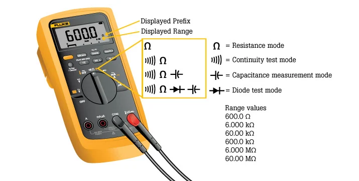
Set the multimeter to the resistance measurement mode (usually marked as Ω).
-
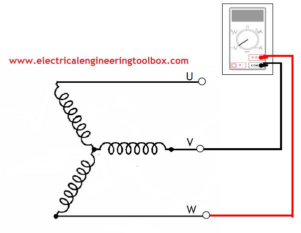
Connect the probes to the terminals of the windings, for example, U1 and U2, and record the resistance value.
-
The same should be done for V1-V2 and W1-W2, and it should be checked that the three-phase resistance value is about the same. If one phase resistance is much larger, it may be due to insulation aging or localized damage in this winding. If the reading is zero, this indicates an inter-turn short circuit.
For example, the technicians, in one routine check, found the resistance between U1 and U2 was 15 ohms, while between V1-V2 and W1-W2, it gave only 12 ohms; this would show that the winding of the U-phase might be aging and hence making the motor consume more energy.
Points to note:
-
If the resistance is close to zero or infinite, it indicates a short circuit or open circuit in the winding, requiring further inspection.
-
Among such conditions are high humidity that might dampen the insulation of the winding and thereby give a different resistance reading than what is real, and it is better to conduct this test in a dry environment.
Determine Winding Start and End
Terminal box markings usually give direct information on the start and end points of the windings, such as U1, U2, V1, V2, W1, W2. In many cases, these markings are not clear, destroyed, or missing, thus one cannot directly find out the start and end points of the windings. In that case, the points must be found by other methods.
Method 1: Low Voltage DC Current Inductance Direction Test
An effective method to test the start point of the winding is using low-voltage DC current inductance direction. The steps are as follows:
-
Prepare the DC power supply: Use a 12V DC regulated power supply to ensure that the voltage is stable.
-
Connect the power supply to the winding end: Connect the positive pole of the DC power supply to either end of the winding (e.g. U1).
-
Measure the voltage at the other end: At the other end of the winding (e.g. U2), use a voltmeter to measure the voltage polarity.
-
Determine the start point: If the voltage polarity shown on the voltmeter matches the direction of the applied current, the measured end is the start point of the winding. If the polarity is reversed, the opposite end is the start point.
Method 2: Magnetic Field Induction Method
The determination of the sequence and start point using the magnetic field induction method will be workable in those cases when direct confirmation via marking is impossible. The described approach is based on the magnetic field that will arise from the three-phase current passed through the windings; this direction of the magnetic field can be observed using the magnetic needle. Steps to be followed:
-
Energize the windings one by one: Pass a small current for a short time through each of the three-phase windings—one after the other, say U1, V1, W1—so that too much heat does not build up in the windings.
-
Observe the magnetic needle deflection: After every energizing, a small magnetic needle shows the direction of deflection. The current flowing through each winding will set up a specific magnetic field, and the magnetic needle will be deflected depending upon the direction of the magnetic field.
-
Record the deflection direction: Note the direction of deflection for the magnetic needle of each winding. Most often, more than 90% of the windings will indicate the same deflection patterns, which means that the phase order and start points for those windings are correct.
-
Determine the winding sequence and start point: From the direction of deflection and its consistency, the right sequence and start point can be derived for the windings. If there are inconsistencies in the readings, you may want to check the connections of the windings again or your test equipment.
Perform Power-On Testing
Before testing, the motor should be connected to the proper power source. For most industrial three-phase motors, 380V or 480V three-phase power is used. Please refer to the specific power requirements on the motor nameplate. Pay special attention to ensuring the motor wiring matches the specifications of the power source to avoid equipment damage or electrical safety incidents.
Before energizing, test insulation resistance of the windings with an insulation tester. The insulation resistance of them shall not be less than 1MΩ. If less, the insulation is too low and the insulation could lead to a short-circuit or electric shock threat—the motor should be taken out of service immediately to make repairs.
Powered on, check the operation status of the motor, especially if its rotation direction is correct. Standard three-phase motors are supposed to rotate either counterclockwise or clockwise. If it is found to be reversed, just change any two phases of the motor into different colors.
Testing focuses:
-
Balanced three-phase current: Use a clamp meter to measure three-phase current. The difference between them should not be greater than 10%. For example, an average of 24-26A for a 15kW motor is normal. If there is a big imbalance in one phase, switch off the power immediately and check the winding connections or wiring issues.
-
Check temperature and noise: During operation, pay attention to the temperature of the windings. The surface temperature of the windings shall not be higher than 80°C, but the exact temperature limit should be confirmed based on the motor’s insulation class. If the temperature rises too quickly or exceeds the rated value, immediately stop testing. Also, monitor any noise during operation. Abnormal noises include sharp or irregular sounds, which are usually indicative of a mechanical or electrical fault such as bearing wear, winding short circuits, or unbalanced rotors.
Points to note:
-
Power-on testing should be limited to 5 minutes, especially when the load is not connected, to prevent excessive idling that may cause winding overheating or bearing damage.
-
If abnormalities are detected during testing (e.g., rapid temperature rise, significant current fluctuation, or sharp noise), immediately turn off the power and investigate the cause.
Identify by Winding Color Codes
Winding color codes give an easy, efficient method for identifying three-phase motor windings. Under IEC, the general color used for the start points of the three-phase windings is red, yellow, and blue for U1, V1, W1, respectively, while black, white, and green are generally used for the ends of the windings, U2, V2, W2. Indeed, over 70% of industrial motors use this color marking, especially in new equipment where the standard is stricter. However, older equipment might be faded in color or nonstandard and will need additional confirmation.
When inspecting, carefully check the color markings inside the terminal box and note the color and position of each wire. For windings with unclear colors, you can verify them with the following methods:
-
Use a multimeter: The resistance can be measured between red-yellow-blue, usually in the range of 5-50 ohms. Any big deviation in resistance could signal incorrect wiring or damage to the windings. Note that resistance measurements confirm mainly the integrity of the windings and not the start or end points.
-
Perform power-on testing: Observe the direction of rotation and the balance of the currents of the motor; combine these with colour markings for further identification. Let the current deviation of each phase not exceed 10% and check if the motor rotates as it should. In case of current imbalance or wrong direction, you may change the wiring correspondingly.
Marking materials used in such cases should be high-temperature-resistant and corrosion-proof to ensure that markings are effective for a long period. Though color codes are simple and intuitive, when the markings are not clear, it is critical that they be validated with scientific tools to ensure safety and accuracy.